How Compact Discs are made?
Abstract
As the major media for music distribution for over 25 years, compact disc is about to reach the end of its life cycle. But if you are a music lover and CD collector, you may still be interested in knowing how compact discs are made. In this paper the author will try to explain the whole process on how a compact disc is fabricated, from the raw material to the finished product.
Introduction
On the surface, a compact disc looks like a gleaming mirror on one side, and some ornamental painting on the other side. I was intrigued by the amount of music a small disc could hold when I received my first CD player as a Christmas gift. Since then I have always wanted to know what makes a CD sound. Searching the Internet one would not be difficult to find literatures on this area. Unfortunately most are written in the language difficult to be understood by the laymen -- the outsiders of the CD and DVD replication industry.
Coincidently I need to pick a subject for my science project at the Mountain View Los Altos High School. I chose to digest the information on the Internet about this subject and rewrite in more simple terms so anyone can understand.
The overall workflow
Making a compact disc is a complicated process with a lot of details. But in general the process can be divided into these following broad areas.
- Polishing of glass master to get a super smooth surface
- Coating of the glass master with light sensitive material.
- Transferring of digital data to the light sensitive film on the glass master.
- Developing of the light sensitive film with chemical.
- Electroplating of the glass master to obtain a stamper
- Injection of molten polycarbonate onto the stamper
- Sputtering of the clear disc with reflective material such aluminum
- Varnishing of the disc with lacquer as protection
- Printing of artwork
In the following sections each of these steps will be elaborated.
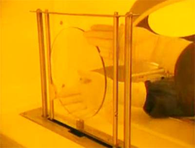
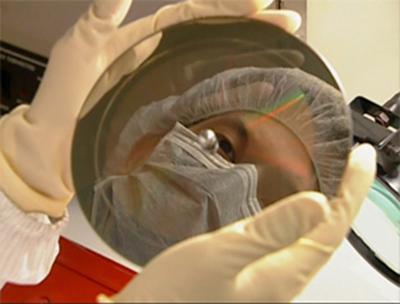
About the glass master
A glass master is a very delicate piece. The requirements for a glass master are very stringent. Listed below are the minimum requirements that a glass master has to meet.
- Diameter: 士 0.02mm
- Thickness: 1.6 土 0.02mm
- Roundness: ≤ 10 μm
- Flatness: ≤ 10 μm
- Parallilism: ≤ 10 < μm (The difference between the thickest and the thinnest)
- Surface roughness: Ra ≤ 10 μm
- Free from follow defects:
- Breaks and penetrating cracks
- Surface chips
- Bubbles and opaque inclusion
- Residual lapping damage
- Scratches
- Defect by polishing and pits
- Ultrasonic damage
- Finger prints, glove prints
- Contaminations and dust
- Surface corrosion
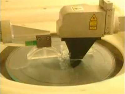
Glass substrate polishing
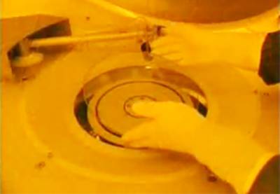
The glass substrate is first cleaned with ultrasound. For making sure there will not be dirt during the polishing process, the glass substrate needs to be electrostatics free. Once the de-statics is done, the glass substrate will undergo the polishing in a controlled environment. Using SiO2 with Ra ≤ 0.5μm as the abrasive agent, the glass substrate will be buffed to the desire smoothness, i.e. Ra ≤ 10μm.
Coating of the glass master with light sensitive material (aka RMP)
RMP stands for Resist Mastering Preparation. In this step, a thin primer is applied to the glass substrate when it is spinning in high speed. The primer functions as adhesive to bond with the later applied photo sensitive coating. Once the primer is dried, another thin layer of photoresist coating is applied. The glass substrate is then transferred to an oven and baked for about 30 minutes at 90 Co.
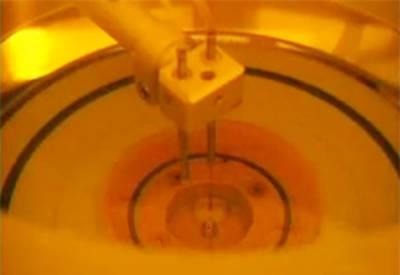
Transferring of digital data to the photoresist film (aka LBR)
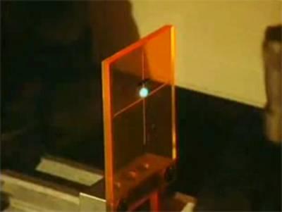
LBR stands for Laser Beam Recording and is the most important step in the whole process. In this step digital signal of the master is converted, through the Mastering Interface System, into high frequency signal and sent to the mastering reader. It also drives the laser beam to mark on the light resisting material on the glass substrate. Source data can come from DDP file, 8mm tape such as Exabyte tape, CD-R, DLT tape, etc. Laser beam is normally Kr gas excited with wavelength of 351nm.
Developing of the glass master with chemical
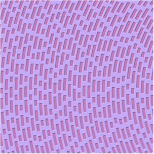
This is the step to develop the digital signal on the light resisting substrate. Chemical solution is used to wash away the part exposed to the laser, forming the pits and the lands. The chemical solution used is usually alkaline. Its function is to dissolve the light resisting material hit by the laser beam.
Electroplating of the glass master to obtain a stamper
Since the glass master is too fragile to be used as an injection mold, a metal mold called a stamper is usually used.
Making a stamper from the glass master involves the metallization of the glass master and later galvanizing it with electroforming. The purpose of having a thin metal layer is to create the electrode for electroforming which thickens the metal to form the stamper.
To metalize to glass master the glass substrate is loaded into a “Load Lock Chamber” and the chamber should be in class one vacuum. The Load Lock Chamber is for preparation only. The main work is done in the Process Chember where class 2 vacuum is required. The material of the coating is usually Ni-V alloy target.
Through electroforming the metal layer is thickened from 150nm to 300μm. This is the thickness of the metal stamper used in replication. Electroforming uses the same principle of electroplating. Once done, the metal will be separated from the glass substrate. Three electrolyte solutions are used in the process, Nickel sulfamate is the main media for carrying the Ni+ ions from the positive gate to the negative charged plate. Boric acid is used to balance the pH value. Nickel Chloride is used to stabilize the concentration of the Ni+ ions. If the Ni+ ions are depleted, the final stamper will have defects.
The stamper created this way, i.e. from the glass master is called the Father stamper. It can be mounted for disc injection directly. However, it is not uncommon that the father stamper is further used to create a negative stamper called the Mother stamper. Mother stampers cannot be used for disc injection. Mother stampers are used to create the Son stampers which have the same pits and lands as the father stamper. Normally one father stamper can be used to create three mother stampers and each of these mother stampers can be used to create three son stampers. Each positive stamper, be it the father or the son stamper, can be used to mold about 30,000 discs. So (1 + 9) x 30,000 = 300,000. If a replication job requires more than 300,000 discs then there will be the need to create two or more glass masters.
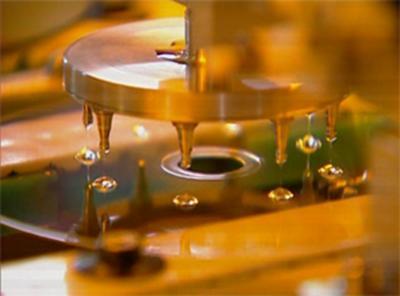
Injection of molten polycarbonate onto the stamper
A father stamper or a son stamper can be mounted to the automatic injection machine. Molten polycarbonate is then injected into the chamber where the stamper is mounted. A clear piece of plastic in the shape and size of a compact disc is then formed. The disc now has all the pits and lands of the digital signal of the original master.
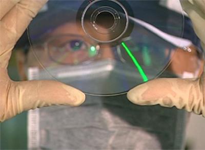
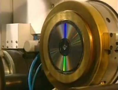
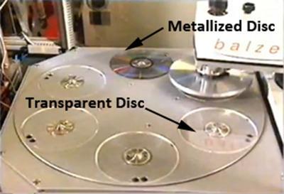
Sputtering of disc with aluminum coating
After leaving the molding machine, the disc is wholly formed but transparent; a player’s laser beam can not read the impressed data because there would be no reflected beam to convey the information. Hence a reflective layer must be placed over the data pits. The reflective layer, typically aluminum, is very thin � on the order of 50 to 100 nm thick.
A cold solid target is bombarded with ions, releasing metal molecules which coat the disc. Using high voltages, a discharge is formed between a cathode target and an anode. Powerful permanent magnets behind the cathode form a concentrated plasma discharged immediately above the target area. Argon ions are extracted from the plasma. They bombard the target surface, thus sputter it.
To protect this thin layer from physical damage such as scratches and oxidation, an acrylic plastic layer is applied over it as varnishing.
Printing of artwork
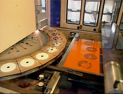
With all the steps so far a working CD has been made. The CD can then be silkscreen or offset printed with artwork. Silkscreen is normally used for vector graphics for better color matching. Offset is used for photographic artwork using CMYK as the basic color elements. Once the artwork is printed, the disk will be exposed to a high intensity UV lamp which dries the ink instantly. The discs are stacked and then transported for packaging.
Conclusion
Seeing and learning how compact discs are manufactured is absolutely educational. The whole process from the beginning to the end requires knowledge from physics, chemistry, and statistics. System engineering also plays a key role in the whole manufacturing cycle. The timing and coordination among steps have to be very precise. With combination of manual and automatic quality control the defect rate can be controlled at one per million.
Acknowledgement
I would like to thank the staffs of New Cyberian for showing me the steps on making a compact disc from the beginning to the end. The knowledge I gained is so valuable and it can never be learned from the classrooms. Thanks New Cyberian!